This article is about a breathalyzer
circuit using 8051 microcontroller which outputs the blood alcohol
content (BAC) from the breath. The BAC is displayed in percentage on a 3
digit seven segment display. The microcontroller used if AT89S51 which
belongs to the 8051 family and the alcohol sensor is MQ135 gas sensor
from Futurelec.
MQ135 gas sensor.
MQ135 is a stable and sensitive gas
sensor which can detect ammonia, carbon dioxide, alcohol, smoke,
nitrogen dioxide etc. The sensor consists of a tin dioxide sensitive
layer inside aluminium oxide micro tubes, measuring electrode and a
heating element inside a tubular aluminium casing. The front end of the
sensor is covered using a stainless steel net and the rear side holds
the connection terminals.
The ethyl alcohol present in the breath
is oxidized into acetic acid while passing over the heating element.
This ethyl alcohol falls on the tin dioxide sensing layer and as a
result its resistance decreases. This resistance variation is converted
into a suitable voltage variation using an external load resistor. The
typical connection arrangement of an MQ135 alcohol sensor is shown
below.
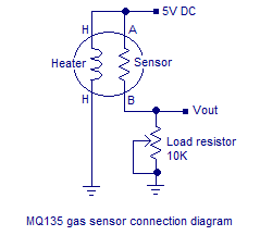
MQ135 alcohol sensor
MQ135 has different resistance values at
different temperature and different concentration of gases. The
manufacturer recommends to calibrate the sensor at 100ppm of ammonia or
50ppm of alcohol. The recommended value of the load resistor is between
10K to 47K.
Circuit diagram.
Breathalyzer using 8051
The voltage output of the alcohol sensor is converted into a digital format using the ADC0804 (IC1). The Vref/2 pin of the ADC is held at 1.28V using the voltage divider network made of R14 and R15. Vref/2
=1.28V means the step size of the ADC will be 10mV and the output of
the ADC will increment by one bit for every 10mV increment in the analog
input. Refer the datasheet of ADC0804 for a better grasp. Digital out
of the ADC (D0 to D7) is interfaced to Port1 of the microcontroller.
Control signals CS, RD, WR, INTR are obtained from the microcontrollers
P3.7, P3.6, P3.5, P3.4 pins respectively. R9 and C1 are associated with
the clock circuitry of the ADC0804.
Capacitor C3 connected between Vin+ and Vin-
of the ADC0804 filters of noise (if any) in the sensor output. If C3 is
not used the digital output of the ADC will not be stable. This filter
capacitor will surely induce some lag in the ADC response but it is not
very relevant in this entry level application. The microcontroller
performs required manipulations on the ADC digital output in order to
convert it into BAC % and displays it on the three digit seven segment
display. Port0 of the microcontroller is interfaced to the multiplexed
three digit seven segment display. The drive signals for the threes
digits are obtained from the microcontroller’s P3.0, P3.1, P3.2 pins
respectively.
Program.
ORG 00H
MOV P1,#11111111B
MOV P0,#00000000B
MOV P3,#00000000B
MOV DPTR,#LUT
MAIN: MOV R4,#250D
      CLR P3.7
      SETB P3.6
      CLR P3.5
      SETB P3.5
WAIT: JB P3.4,WAIT
      CLR P3.7
      CLR P3.6
      MOV A,P1
      MOV R5,A
      SUBB A,#86
      JC NEXT
      SETB P3.3
      CLR PSW.7
NEXT: MOV A,R5
      SUBB A,#115D
      JNC LABEL
      MOV A,#00000000B
      CLR PSW.7
LABEL: MOV B,#5D
       MUL AB
       MOV B,#8D
       DIV AB
       MOV B,#10D
       DIV AB
       MOV R6,A
       MOV R7,B
DLOOP:SETB P3.0
      MOV P0,#01000000B
      ACALL DELAY
      CLR P3.0
      SETB P3.1
      MOV A,R6
      ACALL DISPLAY
      MOV P0,A
      ACALL DELAY
      CLR P3.1
      SETB P3.2
      MOV A,R7
      ACALL DISPLAY
      MOV P0,A
      ACALL DELAY
      CLR P3.2
      DJNZ R4,DLOOP
      SJMP MAIN
DELAY: MOV R3,#255D
LABEL1: DJNZ R3,LABEL1
        RET
DISPLAY: MOVC A,@A+DPTR
         CPL A
         RET
LUT: DB 3FH
     DB 06H
     DB 5BH
     DB 4FH
     DB 66H
     DB 6DH
     DB 7DH
     DB 07H
     DB 7FH
     DB 6FH
END
Notes.
- The MQ135 gas sensor requires around 5 minutes of preheat before the first use.
- The MQ135 takes few minutes to retrace back to its normal condition after a positive test (alcohol present in the breath).
- If there is no alcohol in the breath the sensor output will swing back to its normal condition very fast.
- Read these articles Interfacing seven segment display to 8051 microcontroller , Interfacing ADC to 8051 microcontroller before attempting this project.
- This breathalyzer circuit is just an entry level one and is not suitable for high end applications such as law enforcement or laboratory application.
- The logic for converting the digital output of ADC into BAC percentage was obtained using approximation techniques.

0 comments:
Post a Comment